User:John R. Brews/Sample: Difference between revisions
imported>John R. Brews No edit summary |
imported>John R. Brews No edit summary |
||
| Line 4: | Line 4: | ||
==Finding the Thévenin components== | ==Finding the Thévenin components== | ||
To determine the Thévenin voltage, open circuit | To determine the Thévenin voltage, open circuit the two terminals and measure or calculate the open-circuit voltage across the terminals. | ||
To determine the Thévenin impedance, set all independent sources between the two terminals (leave the ''dependent sources'' active), and determine the impedance seen looking into the two terminals. For example, apply a known voltage across the terminals and measure the current drawn, or apply a known current and determine the voltage developed. The Thévenin impedance is then the ratio of the voltage across the terminals to the current passing through the terminals. | To determine the Thévenin impedance, set all independent sources between the two terminals (leave the ''dependent sources'' active), and determine the impedance seen looking into the two terminals. For example, apply a known voltage across the terminals and measure the current drawn, or apply a known current and determine the voltage developed. The Thévenin impedance is then the ratio of the voltage across the terminals to the current passing through the terminals. | ||
In the case of a frequency dependent applied voltage or current, the impedance may be dependent upon frequency and exhibit a phase dependent upon frequency, as normally expressed using an impedance represented by a complex number. | In the case of a frequency dependent applied voltage or current, the impedance may be dependent upon frequency and exhibit a phase dependent upon frequency, as normally expressed using an impedance represented by a complex number. | ||
==Example== | |||
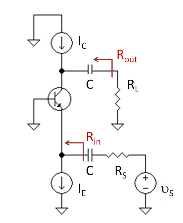
{{Image|Bipolar voltage amplifier.PNG|right|2000px|A bipolar voltage amplifier.}} | |||
==References== | ==References== | ||
Revision as of 10:11, 21 May 2011
{{TOC|right}
In the theory of electrical circuits, Thévenin's theorem allows the replacement of a two-terminal portion of a linear circuit by a simplified circuit consisting of a voltage source, called the Thévenin voltage source, in series with an impedance, called the Thévenin impedance. Thévenin's theorem is the dual of Norton's theorem, which replaces a two-terminal portion of a linear circuit by a simplified circuit consisting of a current source in parallel with an impedance.[1]
Finding the Thévenin components
To determine the Thévenin voltage, open circuit the two terminals and measure or calculate the open-circuit voltage across the terminals.
To determine the Thévenin impedance, set all independent sources between the two terminals (leave the dependent sources active), and determine the impedance seen looking into the two terminals. For example, apply a known voltage across the terminals and measure the current drawn, or apply a known current and determine the voltage developed. The Thévenin impedance is then the ratio of the voltage across the terminals to the current passing through the terminals.
In the case of a frequency dependent applied voltage or current, the impedance may be dependent upon frequency and exhibit a phase dependent upon frequency, as normally expressed using an impedance represented by a complex number.
Example
References
- ↑ Adel S Sedra and Kenneth C Smith (1998). “Appendix E: Some useful network theorems”, Microelectronic circuits, 4rth ed. Oxford University Press, pp. E-1 ff. ISBN 0-19-511690-9.
