Diffraction: Difference between revisions
imported>Boris Tsirelson (→Real-life example: link) |
mNo edit summary |
||
| (12 intermediate revisions by 3 users not shown) | |||
| Line 1: | Line 1: | ||
{{subpages}} | {{subpages}} | ||
'''Diffraction''' is a physical phenomenon due to which waves passing through small openings will tend to 'bend' towards the edges. Diffraction applies to virtually all kinds of waves including sound, light, and other [[electromagnetic wave]]s (such as [[radio]] waves). The phenomenon is particularly interesting because of the interference patterns that arise from such waves. It puts a limit to the theoretical resolution of optical systems. It is also a convincing piece of evidence for the wave nature of light. | '''Diffraction''' is a physical phenomenon due to which waves passing through small openings will tend to 'bend' towards the edges. Diffraction applies to virtually all kinds of waves including sound, [[light]], and other [[electromagnetic wave]]s (such as [[radio]] waves). The phenomenon is particularly interesting because of the interference patterns that arise from such waves. It puts a limit to the theoretical resolution of optical systems. It is also a convincing piece of evidence for the wave nature of light. | ||
== Simple cases == | == Simple cases == | ||
| Line 7: | Line 7: | ||
=== The single slit === | === The single slit === | ||
The simplest example of diffraction is the single slit experiment. A laser is set up pointing against a small rectangular slit in an otherwise opaque screen. Some distance behind the slit is a screen on which the diffraction pattern can be observed. The slit has a width ''b'' and a height which is large in comparison | The simplest example of diffraction is the single slit experiment. A laser is set up pointing against a small rectangular slit in an otherwise opaque screen. Some distance behind the slit is a screen on which the diffraction pattern can be observed. The slit has a width ''b'' and a height which is large in comparison to ''b'', and the components are sufficiently far away from each other that the waves are approximately plane (straight wavefronts). On the screen we observe a pattern of 'dots', with an intense central maximum in the middle and auxiliary maxima on both sides of it, intensity rapidly decreasing as we move away from the centre. We note that the central maximum is twice as wide as the others. If the width ''b'' of the slit is made smaller, the pattern will spread out in the horizontal direction. After application of the [[principle of superposition]], we arrive at the following formula for the n:th minimum: | ||
:<math>b \sin \theta = n \lambda \!</math> | :<math>b \sin \theta = n \lambda \!</math> | ||
Where ''b'' is the width of the slit, ''θ'' is the angle made with the line | Where ''b'' is the width of the slit, ''θ'' is the angle made with the optical axis (the straight line through the slit), ''n'' is a positive [[integer|whole number]], and ''λ'' is the [[wavelength]] of the diffracted wave. A detailed derivation of the forumla is available [[#Geometric derivation of the single slit formula|below]]. We also obtain an expression for the intensity in a point at angle ''θ'': | ||
{{Image|Diffraction-intensity.png|right|300px|The intensity pattern from a single slit.}} | {{Image|Diffraction-intensity.png|right|300px|The intensity pattern from a single slit.}} | ||
| Line 49: | Line 49: | ||
=== Mathematical interpretation of the Rayleigh criterion === | === Mathematical interpretation of the Rayleigh criterion === | ||
We have a formula for the first minimum from ''A'': | Our goal is to find a mathematical formulation of the Rayleigh criterion for resolution. We will limit ourselves to optical systems that are in a vacuum. We have a formula for the first minimum from ''A'': | ||
: <math>d \sin \theta = 1.22 \lambda \!</math> | : <math>d \sin \theta = 1.22 \lambda \!</math> | ||
| Line 71: | Line 71: | ||
=== Real-life example === | === Real-life example === | ||
Suppose that we want to find the maximum theoretical resolution of a digital camera. The camera has a lens with a focal length of 100 mm, and an aperture (circular opening) of <math>100 / 4 = 25</math> mm . We are considering only visible light, why we assume a wavelength of 550 nm (corresponding to green light, in the middle of the visible spectrum). We are now ready to find the maximum resolution: | Suppose that we want to find the maximum theoretical resolution of a digital [[camera]]. The camera has a lens with a focal length of 100 mm, and an aperture (circular opening) of <math>100 / 4 = 25</math> mm . We are considering only visible light, why we assume a wavelength of 550 nm (corresponding to green light, in the middle of the visible spectrum). We are now ready to find the maximum resolution: | ||
: <math>d \theta = 1.22 \lambda \quad \Longleftrightarrow \quad \theta = \frac{1.22 \lambda}{d}</math> | : <math>d \theta = 1.22 \lambda \quad \Longleftrightarrow \quad \theta = \frac{1.22 \lambda}{d}</math> | ||
Inserting values into the formula, we find the minimum angular separation to be 2.684 × 10<sup>-5</sup> [[radian]]s. Since modern digital cameras use [[CCD]] devices with small photosites or '[[pixel]]s' to capture images, we can make another approximation. For two objects to be resolved by a digital camera, their images must end up at least one photosite apart. Assuming a distance of 50 mm from the lens to the image sensor, we calculate: | Inserting values into the formula, we find the minimum angular separation to be 2.684 × 10<sup>-5</sup> [[radian]]s. Since modern digital cameras use [[Charge-coupled device|CCD]] devices with small photosites or '[[pixel]]s' to capture images, we can make another approximation. For two objects to be resolved by a digital camera, their images must end up at least one photosite apart. Assuming a distance of 50 mm from the lens to the image sensor, we calculate: | ||
: <math>\theta = \frac{h'}{\ell '} \quad \Longleftrightarrow \quad h' = \theta \ell '</math> | : <math>\theta = \frac{h'}{\ell '} \quad \Longleftrightarrow \quad h' = \theta \ell '</math> | ||
| Line 81: | Line 81: | ||
giving a length separation on the sensor of 673.6 nm. We are now interested in the maximum resolution of such a sensor. Most professional cameras take photographs in the 3:2 format (pictures are half again as wide as they are high). One common sensor size is the [[APS-C]] format, which is about 25.1 mm wide and 16.7 mm high. Thus, we calculate the maximum amount ''n'' of photosites in a row of 25.1 mm, giving a separation of 673.6 nm: | giving a length separation on the sensor of 673.6 nm. We are now interested in the maximum resolution of such a sensor. Most professional cameras take photographs in the 3:2 format (pictures are half again as wide as they are high). One common sensor size is the [[APS-C]] format, which is about 25.1 mm wide and 16.7 mm high. Thus, we calculate the maximum amount ''n'' of photosites in a row of 25.1 mm, giving a separation of 673.6 nm: | ||
: <math> n = \frac{width}{h'} = \frac{25.1 \times 10^{-3}}{673.6 \times 10^{-9}}</math> | : <math> n = \frac{\mathrm{width}}{h'} = \frac{25.1 \times 10^{-3}}{673.6 \times 10^{-9}}</math> | ||
which gives a total of 37,000 photosites on a row. Given that the sensor is in a 3:2 format, we calculate the total number of photosites as 925,000,000. In camera manufacturer terminology, this is the equivalent of 925 megapixels. | which gives a total of 37,000 photosites on a row. Given that the sensor is in a 3:2 format, we calculate the total number of photosites as 925,000,000. In camera manufacturer terminology, this is the equivalent of 925 megapixels. | ||
| Line 97: | Line 97: | ||
{{Image|Diffraction-phasediff.png|right|250px|In a phase difference of a wavelength, there are ray-pairs such that their magnitudes are equal and opposite, and thus add up to zero.}} | {{Image|Diffraction-phasediff.png|right|250px|In a phase difference of a wavelength, there are ray-pairs such that their magnitudes are equal and opposite, and thus add up to zero.}} | ||
We are thus looking for the angle <math>\theta</math> where this path difference (and thus phase difference) causes complete destructive interference. We note that in a phase difference of a full period, we can construct ray-pairs which have the exact opposite phase and equal amplitude. For each ray with a positive amplitude <math>A</math> there exists another ray within the interval which has the opposite magnitude <math>-A</math>. This leads to the conclusion that when the phase difference <math>\delta</math> equals a whole number of wavelengths, there will be total destructive interference. Thus, it seems clear that the path difference <math>\delta</math> we are looking for is a whole number of wavelengths. | We are thus looking for the angle <math>\theta</math> where this path difference (and thus phase difference) causes complete destructive interference. We note that in a phase difference of a full period, we can construct ray-pairs which have the exact opposite phase and equal amplitude. For each ray with a positive amplitude <math>A</math> there exists another ray within the interval which has the opposite magnitude <math>-A</math>. This leads to the conclusion that when the phase difference <math>\delta</math> equals a whole number of wavelengths, there will be total destructive interference. Thus, it seems clear that the path difference <math>\delta</math> we are looking for is a whole number of wavelengths. Hence, we are ready to formulate a criterion for single-slit diffraction minima: | ||
:<math>b \sin \theta = m \lambda, \qquad m = \pm 1, \pm 2 ...</math> | :<math>b \sin \theta = m \lambda, \qquad m = \pm 1, \pm 2 ...</math> | ||
| Line 114: | Line 114: | ||
''Spectrographs, ...'' | ''Spectrographs, ...'' | ||
== Bibliography == | |||
* Jönsson & Nilsson, 2010, ''Våglära och optik'' (Wave theory and optics), fourth edition, fourth imprint. | |||
* Watt, Ian M., 1997, ''The principles and practice of electron microscopy'', Cambrigde University Press, second edition. | |||
<references/>[[Category:Suggestion Bot Tag]] | |||
Latest revision as of 06:01, 7 August 2024
Diffraction is a physical phenomenon due to which waves passing through small openings will tend to 'bend' towards the edges. Diffraction applies to virtually all kinds of waves including sound, light, and other electromagnetic waves (such as radio waves). The phenomenon is particularly interesting because of the interference patterns that arise from such waves. It puts a limit to the theoretical resolution of optical systems. It is also a convincing piece of evidence for the wave nature of light.
Simple cases
The single slit
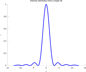
The simplest example of diffraction is the single slit experiment. A laser is set up pointing against a small rectangular slit in an otherwise opaque screen. Some distance behind the slit is a screen on which the diffraction pattern can be observed. The slit has a width b and a height which is large in comparison to b, and the components are sufficiently far away from each other that the waves are approximately plane (straight wavefronts). On the screen we observe a pattern of 'dots', with an intense central maximum in the middle and auxiliary maxima on both sides of it, intensity rapidly decreasing as we move away from the centre. We note that the central maximum is twice as wide as the others. If the width b of the slit is made smaller, the pattern will spread out in the horizontal direction. After application of the principle of superposition, we arrive at the following formula for the n:th minimum:
Where b is the width of the slit, θ is the angle made with the optical axis (the straight line through the slit), n is a positive whole number, and λ is the wavelength of the diffracted wave. A detailed derivation of the forumla is available below. We also obtain an expression for the intensity in a point at angle θ:
The circular opening
The double slit
Young's double slit experiment
Diffraction gratings
Theory
Huygen's principle
Waves obey Huygen's principle, which states that all points on a wave front can be seen as sources for new, circular elementary waves. This implies that waves will 'bend around' objects that are in their way, and will also bend around corners that they pass. Think of a wave in a water surface, and how it behaves when meeting a pole that rests in the water. It is a fact that the amount of bending varies with the wavelength, such that longer wavelengths bend more strongly. For that reason, your voice appears darker to you than to others, because more of the lower sounds (longer wavelengths) will bend around your head and reach your ears.
Babinet's principle and complimentary patterns
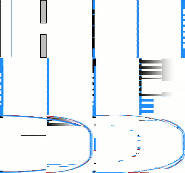
Two pairs of complimentary patterns.
A complimentary pattern is the inverse of a pattern, so to speak. If P is a pattern that has some opaque areas and some transparent ones, the complimentary pattern P′ is the pattern in which exactly the opposite areas are opaque and transparent. Thus, the complimentary pattern of a single slit is a thread of the same size, and the complimentary pattern of a circular opening is a dot.
If P and P′ are complimentary patterns, Babinet's principle states that the intensity distributions from these are identical. The reasoning behind this is that complimentary patterns together add up to a completely opaque pattern. This means that the diffracted waves from these patterns must add up to zero, implying that waves from these patterns have equal amplitude in each point, but are completely out of phase. The phase of a wave is not visible in an intensity distribution, why the distributions are equal.
Scientists were initially sceptical about this law, since it predicts a bright spot in the middle of the diffraction pattern from, say, a coin of the correct size. This spot was later observed. It matters, however that the pattern is of the correct size depending on the wavelength of the waves used.
Resolution and the Rayleigh criterion
In dealing with optical systems, it is useful to find a limiting case of when a system can just resolve two distinct points. This is given by the Rayleigh criterion. We know that slits and circular openings will cause light to diffract. Since most optical systems consist of circular lenses, we can assume that as a general case. If furthermore we disregard all but the central maxima of diffraction patterns (since the auxiliary maxima are of comparatively small intensity), we will be dealing with two 'spots', one from each point we are trying to resolve. These are called the Airy discs of the points. It turns out that the smallest separation that still allows us to resolve two points A and B is that which causes the center of Airy disc B to coincide with the first minimum from A.
Mathematical interpretation of the Rayleigh criterion
Our goal is to find a mathematical formulation of the Rayleigh criterion for resolution. We will limit ourselves to optical systems that are in a vacuum. We have a formula for the first minimum from A:
If we consider A to lie on the optical axis (directly in front of the lens), we can construct a triangle between A, B, and the center of the lens. This triangle is similar (in the geometric sense) to the triangle between the images of A, B on the viewing screen, and the center of the lens. Thus we find that:
where are the distances from the lens to the objects and to the screen, respectively. h and h' are the distances from the optical axis to the object B and the image of B, respectively.
Applying the small angle approximation that , we get the criterion:
for the minimum separation h between two objects at a distance from the lens-plane of an optical system just barely allowing the objects to be resolved. An alternative formulation is:
for the angular separation of the two objects, independent of the distances involved.
Real-life example
Suppose that we want to find the maximum theoretical resolution of a digital camera. The camera has a lens with a focal length of 100 mm, and an aperture (circular opening) of mm . We are considering only visible light, why we assume a wavelength of 550 nm (corresponding to green light, in the middle of the visible spectrum). We are now ready to find the maximum resolution:
Inserting values into the formula, we find the minimum angular separation to be 2.684 × 10⁻⁵ radians. Since modern digital cameras use CCD devices with small photosites or 'pixels' to capture images, we can make another approximation. For two objects to be resolved by a digital camera, their images must end up at least one photosite apart. Assuming a distance of 50 mm from the lens to the image sensor, we calculate:
giving a length separation on the sensor of 673.6 nm. We are now interested in the maximum resolution of such a sensor. Most professional cameras take photographs in the 3:2 format (pictures are half again as wide as they are high). One common sensor size is the APS-C format, which is about 25.1 mm wide and 16.7 mm high. Thus, we calculate the maximum amount n of photosites in a row of 25.1 mm, giving a separation of 673.6 nm:
which gives a total of 37,000 photosites on a row. Given that the sensor is in a 3:2 format, we calculate the total number of photosites as 925,000,000. In camera manufacturer terminology, this is the equivalent of 925 megapixels.
This is of course only the theoretical maximum resolution. In reality, there are limits due to lens quality, sensor noise and refraction in the air. For more common cameras without exchangeable lenses, the apertures are also much smaller, leading to stronger diffraction. It is a fact, however, that no optical system with an aperture of 25 mm can have a higher resolution.
Geometric derivation of the single slit formula
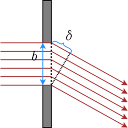
Our goal is to find a mathematical expression for the diffraction minima at an angle from the center axis of a single slit. The single slit has a width and a height that is large enough that vertical diffraction can be neglected. Pointing directly at the slit is a laser sending out parallel rays with wavelength . The maximum path difference is clearly between the two rays passing at the opposite sides of the slit. Constructing a right-angled triangle between the rays, we see that the maximum path difference is:
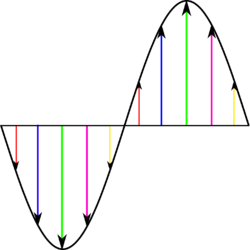
We are thus looking for the angle where this path difference (and thus phase difference) causes complete destructive interference. We note that in a phase difference of a full period, we can construct ray-pairs which have the exact opposite phase and equal amplitude. For each ray with a positive amplitude there exists another ray within the interval which has the opposite magnitude . This leads to the conclusion that when the phase difference equals a whole number of wavelengths, there will be total destructive interference. Thus, it seems clear that the path difference we are looking for is a whole number of wavelengths. Hence, we are ready to formulate a criterion for single-slit diffraction minima:
Quantum-mechanical interpretation
The phenomenon of diffraction can also be understood through the principles of quantum mechanics. Heisenberg's uncertainty principle states that:
which we understand as: The more certain we are about a particle's instantaneous position, the less certain we can be of its instantaneous direction of travel.
Say that we want to pinpoint the location of the beam of light emitted by a laser. We set up a single slit with a width b and a height that is large in comparison with the wavelength of the laser. In order to pass, the light must go somewhere through the slit. Thus, we think that we have pinpointed the location of the light to within b/2 of the center of the slit. Passing through the slit however, the light will spread out and there is no way to predict at what angle a certain photon will go. All we can predict is the probability of photons to go a certain direction, which will generate an even intensity distribution for a large number of photons. Furthermore, the light will spread out even more with smaller widths b (larger certainty in position), which is exactly what Heisenberg predicts.
Applications
Spectrographs, ...
Bibliography
- Jönsson & Nilsson, 2010, Våglära och optik (Wave theory and optics), fourth edition, fourth imprint.
- Watt, Ian M., 1997, The principles and practice of electron microscopy, Cambrigde University Press, second edition.


