Coriolis force
For the psychophysical perception, see Coriolis effect.
The Coriolis force is a force experienced by a object traversing a path in a rotating framework that is proportional to its speed and also to the sine of the angle between its direction of movement and the axis of rotation. It is one of three such inertial forces that appear in an accelerating frame of reference due to the acceleration of the frame, the other two being the centrifugal force and the Euler force. The mathematical expression for the Coriolis force appeared in an 1835 paper by a French scientist Gaspard-Gustave Coriolis in connection with the theory of water wheels, and also in the tidal equations of Pierre-Simon Laplace in 1778.
Although sometimes referred to as an apparent force, it can have very real effects.
Reference frames
Newton's laws of motion are expressed for observations made in an inertial frame of reference, that is, in any frame of reference that is in straight-line motion at constant speed relative to the "fixed stars", an historical reference taken today to refer to the entire universe. However, everyday experience does not take place in such a reference frame. For example, we live upon planet Earth, which rotates about its axis (an accelerated motion), orbits the Sun (another accelerated motion), and moves with the Milky Way (still another accelerated motion).
The question then arises as to how to connect experiences in accelerating frames with Newton's laws that are not formulated for such situations. The answer lies in the introduction of inertial forces, which are forces observed in the accelerating reference frame, due to its motion, but are not forces recognized in an inertial frame. These inertial forces are included in Newton's laws of motion, and with their inclusion Newton's laws work just as they would in an inertial frame. Coriolis force is one of these inertial forces, the other two being the centrifugal force and the Euler force.
These motions are slight, but the Coriolis force does affect aiming artillery pieces and plotting transoceanic air flights. The way Coriolis forces work is illustrated below by a few examples.
Carousel
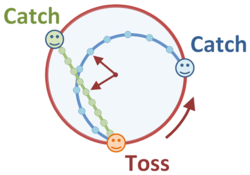
The rotating carousel is perhaps the most common example used to illustrate the effects of rotation upon the formulation of Newton's laws of motion and the introduction of inertial forces into these laws. A simple case is playing catch on the carousel. Standing on the rim of the carousel, a ball is tossed to another player standing at a different position on the rim.
As shown in the figure, from the viewpoint of a stationary observer, the tossed ball is a free body (apart from downward gravity) so its horizontal motion is that of a free body: a straight line at constant speed. The catcher of the ball rotates during the flight of the ball, so the tosser must anticipate just where the catcher will be and tosses the ball toward that future position, rather than directly at the catcher.
From the viewpoint of an observer at the center of the carousel but rotating with it, both the person tossing the ball and the catcher are standing at fixed locations, as they both turn with the carousel. However, the tosser cannot toss the ball directly toward the catcher, because the ball veers off to the right, assuming the carousel in counter-clockwise rotation. To the rotating observer, the curved path means that Newton's laws require a force to cause the ball to curve. The intuitive reaction is that the ball is pushed to the right during flight, and so this force must be countered by throwing the ball somewhat to the left.
From the spacing of the points marked on the figure it may be seen that the ball moves more rapidly for the rotating observer. That can be understood as an increased speed because the carousel is rotating, moving toward the ball. To put it differently, the curved path is longer than the straight one seen by the inertial observer, so the ball has to move faster to cover the curved path in the same time.
For both the rotating and the fixed observer, the distance of the ball from the center of the carousel at any moment in time is exactly the same, as shown by the arrows in the figure that indicate the moment of closest approach of the ball to the center.
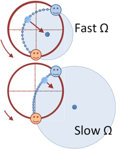
The lower figure illustrates that to the rotating observer the ball executes an approximately circular motion about its center of curvature. The center of curvature of the path is displaced from the center of the carousel by a greater amount the slower the rate of rotation. According to the rotating observer, the ball is subject to a centripetal force directed toward the center of curvature, as shown by the arrow. As the rate of rotation slows to zero, the centripetal force drops to zero as the center of curvature recedes to infinity, and the path is the straight-line toss to the catcher.
Inertial frame
In the stationary frame, the path of the ball is given in x,y coordinates as:
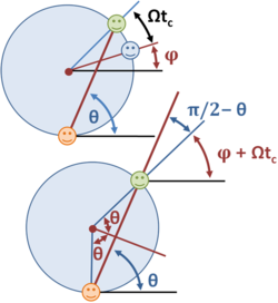
where R is the radius of the carousel, θ is the angle of launch of the ball, v is the speed of launch, and t is the time. At t=0, the tosser is at 6 o'clock, as viewed in the figure, and θ is the angle from the horizontal to the line of throw. The catcher at this time is an angle φ from 3 o'clock. If the carousel turns at the rate Ω, then the catcher has turned from the starting position by an angle Ωtc, placing the catcher in position provided:
where tc is the time of the catch and φ is the starting angle of the catcher. This equation results from the lower diagram and the equality of corresponding angles of parallel lines:
The ball arrives at the rim for the arriving catcher when the path length equals the chord of the circle:
These two equations either determine the angle of launch in terms of a known speed by use of a nonlinear equation or, by assuming a time of catch, the first equation determines the angle of launch and the last equation determines the necessary speed of throw:
Rotating frame
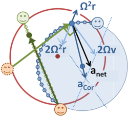
The description in the rotating frame is more complex than in the inertial frame. An approximate approach to the analysis of this case is to observe that for the rotating observer at the center of the carousel, the ball traces a very nearly circular path from the tosser to the catcher. The path has a radius, say ρ, measured from the center of curvature of the path, which is off-center from the carousel. To travel this circular path of radius ρ at a speed v requires a centripetal acceleration v2/ρ, where the speed v is set by the way the ball is tossed in combination with the rotation, and is not the same speed as that seen by the stationary observer, and varies somewhat along the path.
The rotating observer at the center of the carousel always sees a centrifugal force related to the rotation of the carousel. Any object at distance r from the center of rotation is subject to the outward "centrifugal acceleration" Ω2r radial to the center of rotation. This acceleration is not the true centrifugal acceleration of the ball, Ω2ρ, because it is not directed radial to the center of curvature. In addition to this inertial force, if an object is seen by the rotating observer to move with a vector velocity v, it is subject to a Coriolis acceleration aCor = 2v × Ω, which is in the plane of the carousel and perpendicular to the velocity, as shown in the figure. These two inertial forces combine to form a resultant centripetal acceleration actpl with magnitude actpl = Ω2ρ pointing inward to the center of curvature, as required by Newton's laws for circular motion.
This approximate picture is qualitatively correct, but the radius of the path does vary slightly, and the speed of travel around the circular path also varies somewhat. Mathematical details follow.
Mathematical background
The trajectory in the inertial frame (denoted A) is a straight line radial path at angle θ. The position of the ball in (x, y) coordinates at time t is:
assuming the ball is tossed from a 6 o'clock position.
In the turntable frame (denoted B), the x- y axes rotate at angular rate Ω , so the trajectory becomes:
Introducing α as:
the velocity becomes:
If this motion were exactly uniform circular motion, the speed would be constant. Instead, the speed is given by:
To determine the components of acceleration, a general expression is used from the article inertial forces:
in which the term in Ω × vB is the Coriolis acceleration and the term in −Ω × ( Ω × rB) is the centrifugal acceleration. The results are (let α = θ − Ω t):
producing a centrifugal acceleration:
Proceeding with the calculation of the Coriolis force:
producing a Coriolis acceleration:
It is seen that the Coriolis acceleration not only cancels the centrifugal acceleration, but together they provide a net "centripetal", radially inward component of acceleration (that is, directed toward the center of rotation):[1]
An additional component of Coriolis acceleration is perpendicular to rB (t) + R (t), where R (t) = R (sinΩt, cosΩt). The vector rB (t) + R (t) locates the ball from the location of the point of initial toss. This component is:
The "centripetal" component of acceleration resembles that for circular motion at radius rB, while the perpendicular component is velocity dependent, increasing with the radial velocity v and directed to the right of the velocity. The situation could be described as a circular motion combined with an "apparent Coriolis acceleration" of 2Ω v. However, this is a rough labeling: a careful designation of the true centripetal force refers to a local reference frame that employs the directions normal and tangential to the path, not coordinates referred to the axis of rotation.
These results also can be obtained directly by two time differentiations of rB (t). Agreement of the two approaches demonstrates that one could start from the general expression for fictitious acceleration above and derive the trajectories. However, working from the acceleration to the trajectory is more complicated than the reverse procedure used here, which, of course, is made possible in this example by knowing the answer in advance.
Observations
As a result of this analysis an important point appears: all the inertial forces must be included to obtain the correct trajectory. In particular, besides the Coriolis force, the centrifugal force plays an essential role. It is easy to get the impression from verbal discussions of the ball problem, which are focused on displaying the Coriolis force particularly, that the Coriolis force is the only factor that must be considered;[2] emphatically, that is not so.[3] A turntable for which the Coriolis force is the only factor is the parabolic turntable, a concave turntable shaped to provide the centrifugal force of a curved path through its curvature in the manner of a banked turn.
A somewhat more complex situation is the idealized example of flight routes over long distances, where the centrifugal force of the path and aeronautical lift are countered by gravitational attraction.[4][5]
Notes
- ↑ Here the description "radially inward" means "toward the axis of rotation". That direction is not toward the center of curvature of the path, however, which is the direction of the true centripetal force. Hence, the quotation marks on "centripetal".
- ↑ George E. Owen (2003). Fundamentals of Scientific Mathematics, original edition published by Harper & Row, New York, 1964. Courier Dover Publications. ISBN 0486428087.
- ↑ Morton Tavel (2002). Contemporary Physics and the Limits of Knowledge. Rutgers University Press. ISBN 0813530776.
- ↑ James R Ogden & M Fogiel (1995). High School Earth Science Tutor. Research & Education Assoc.. ISBN 0878919759.
- ↑ James Greig McCully (2006). Beyond the moon: A Conversational, Common Sense Guide to Understanding the Tides. World Scientific, 74–76. ISBN 9812566430.


